|
|
|
|
|
|
|
|
|
|
|
|
SUSPENSION SWING ARMS
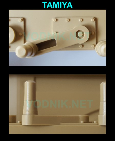
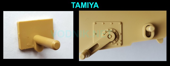
Tamiya kit is the only one in the group with suspension arms molded on the hull tub sides. The hull tub originates from the M1 Abrams kit first released by Tamiya in 1982 and back then such simplification was acceptable. Not anymore... At least setting the correct height of suspension is not a problem in this kit.
The arm is also very simplified and has a recess in it that is not present on the real part.
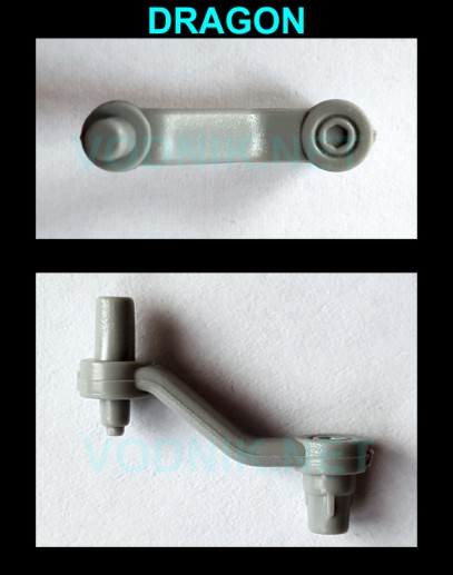
Dragon M1A1 AIM was the first M1 kit with reasonably accurate separate swing arms. Trumpeter released the first M1A1 kit with arms separate, and Dragon M1 Panther II kit also included separate arms, but in both kits they were completely wrong shape. The parts from AIM kit were later used in both M1A2 SEP and SEP V2 kits.
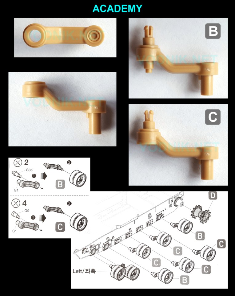
Academy used very interesting and novel way of attaching road wheels in their new M1A2 kit - snap lock pins. The actual swing arms have circular holes in them, into which two types of snap lock pins are inserted. The road wheels have holes of matching diameter in them, so they get securely locked in place during assembly. Just as poly caps, this method allows for removing the wheels (e.g. for painting), but does not require as much space inside the wheel, so it can be made much more accurate.
There is however one problem with Academy swing arms. As I mentioned there are two types of snap lock pin parts. The difference between them is the detail on their rear side. For some reason Academy made some of them (marked as "C" in instruction drawings) flat on the rear... The real parts however are all the same and all have the protruding cylinders on the rear side. I have no idea why Academy made some of their parts inaccurate...
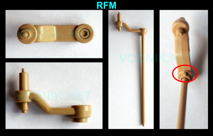
RFM decided to include full length torsion bars in their kit and then... locked them in place, so that they don't work... Not a problem for me, as I always glue torsion bars in place anyway, but it is a bit strange decision. Torsion bars are separate parts in this kit (not shown in photos), so they can just be completely omitted. Also they can probably be made movable by simply removing the small tab marked in the picture.
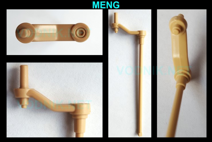
MENG parts look quite similar to the RFM ones at first sight, but this time the torsion bars are molded integrally with swing arms and they are designed to be workable out of the box.
In the images below you can clearly see that Academy made a mistake making some of their swing arm parts flat at the rear.
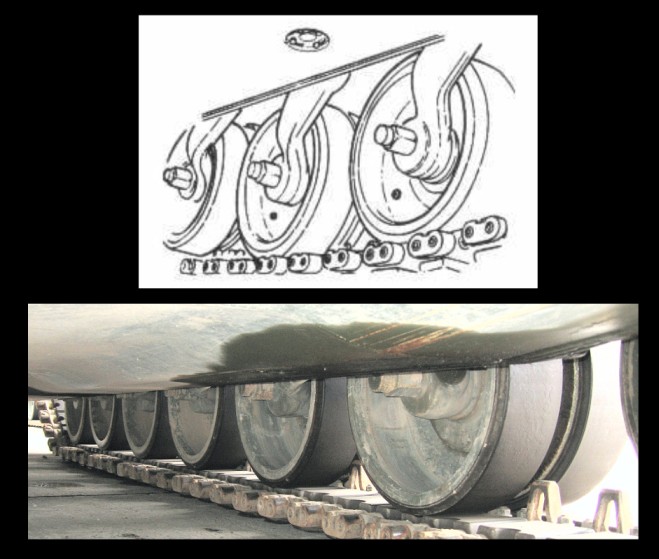
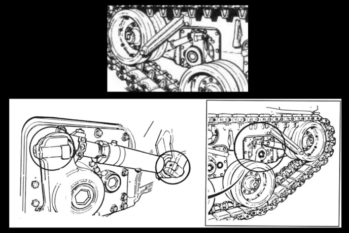
It is difficult to find photos of Abrams swing arms not hidden by wheels, but these two pictures below of damaged tanks show the shape quite well. Looking at these photos I would say that Academy and RFM parts are most accurate in shape. Dragon and Meng arms are close, but not quite correct. Dragon arms not only are bent in a wrong place, but they also seem to be a bit too narrow.
TRACK TENSIONING MECHANISM (IDLER MOUNT)
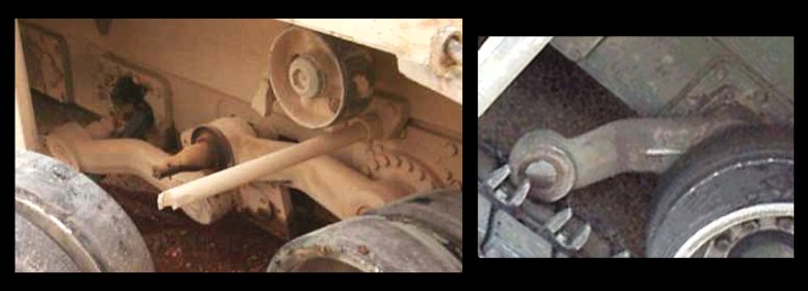
In M1 tanks the track tensioning mechanism is placed between the idler mount and the first road wheel swing arm. Increasing the length of the large screw moves idler further forward and increases the track tension. Thanks to the link between the first road wheel swing arm and the idler arm, the track tension is maintained even when the first road wheel moves up while riding on a rough terrain.
Only the Tamiya kit completely lacks any representation of track tensioning mechanism. Only ugly simple idler axle part is provided. It is one of the reminders of the motorized origins of the Tamiya lower hull parts.
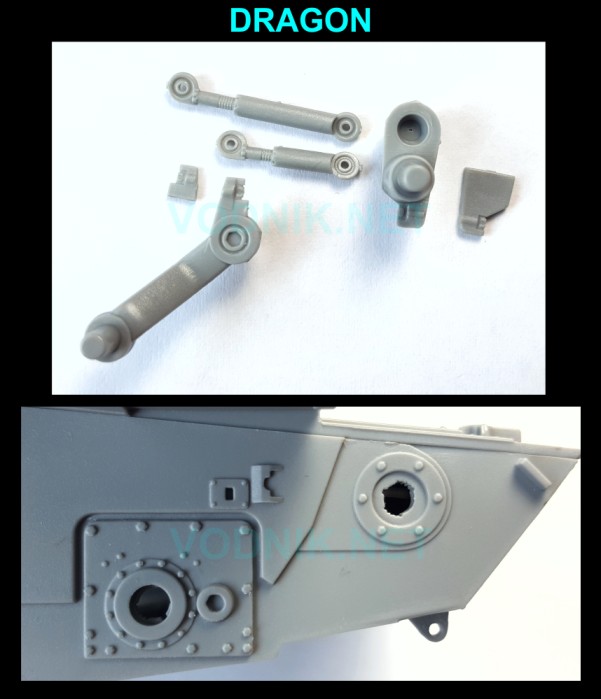
Dragon kit includes complete tensioning mechanism. In the picture below I show both "screws" - for left and right side of the tank, as they are different length. I only show right side versions of other parts, as the left side versions are just mirror copies. As you can see five parts have to be assembled for each side, but the end result is a very good representation of the real parts. While these parts were not meant to be workable, they were designed in such way, to make it easy to modify them to adjust to any position required by the diorama surface shape.
The hole in the idler wheel arm should not be there, but it will be hidden behind the wheel.
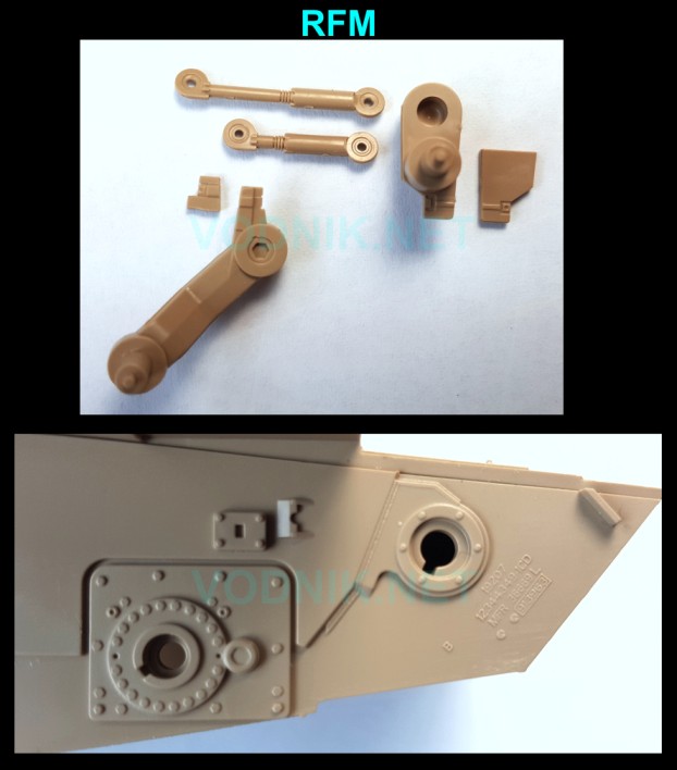
RFM parts are surprisingly (?... I'm repeating myself...) similar to Dragon parts, with one exception - while the lengths of adjustable screws are the same as in the Dragon kit, their design is a bit different, as RFM made the thinner threaded part different length and the thicker cylinder parts the same length. It is not accurate, as you can see in images of real parts further in the article. The idler arm parts have holes in them, identical as Dragon parts.
If you compare the picture of the RFM hull below with the image of Dragon part above you can notice that torsion bar mounting plates are noticeably different between kits - more on this later in the article. In this photo you can also see very nice casting marks detail included only by RFM. What a pity it will be completely hidden on the finished model.
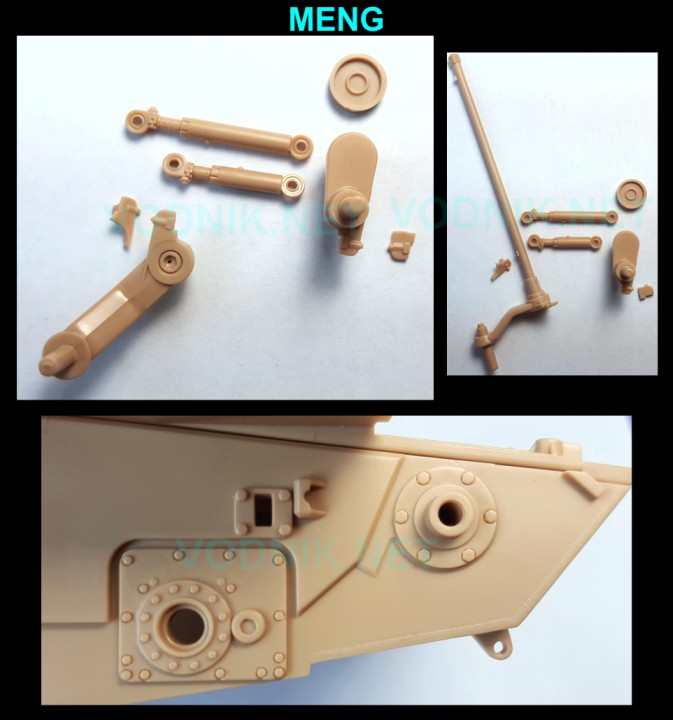
MENG parts are also designed similarly to Dragon parts, but with a bit more details and slightly different engineering. The swing arm for the first road wheel is molded integrally with the torsion bar, and to make it possible for it to actually work, the idler arm is also movable (the circular dish part is glued to the idler arm axle inside the hull tub). For all this to work you must be very careful to put glue only where it is supposed to go. I will glue it all in place in my model.
Academy made modeler's life much easier - they molded entire tensioning mechanism as a single part. All the necessary details are there, so unless you really need the option to adjust the first road wheel and idler wheel positions, this is a very good solution. Small sink holes are visible on parts, but they will be completely hidden behind the idlers.

Below you can see a few photos and technical manual illustrations of the real tank track tensioning mechanism. Take a look at details inside red outlines - as you can see it is the cylinder that is longer on the right side of the tank, not the inner screw part. Interesting why RFM decided to change this one detail and make it inaccurate, when they obviously cop... sorry! "were inspired by" ... Dragon parts engineering.

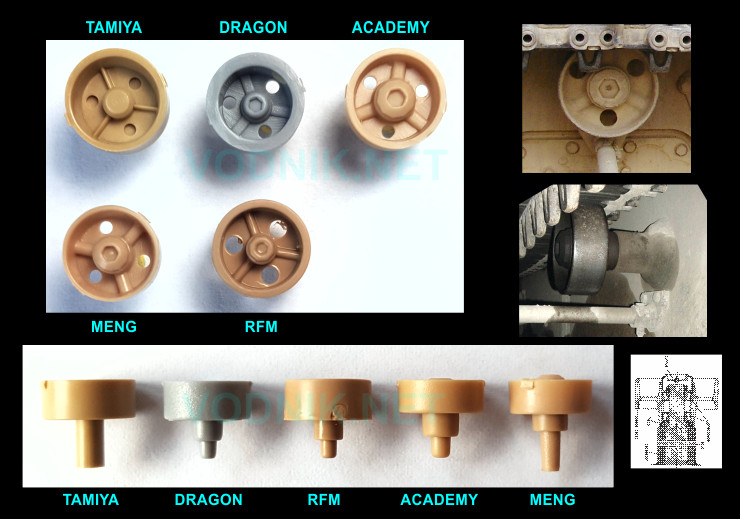
SUPPORT ROLLERS
All M1 family tanks have two track support rollers on each side. Rollers support track behind guide horns. For some reason Tamiya in their kit made axle of front roller longer, so it seats in front of the guide horns. It is not accurate, but maybe it was needed in a motorized version of the kit. The rear roller in Tamiya kit is correctly placed. All the other kits also have rollers correctly placed behind guide horns.
As you can see below Dragon kit part has way too thick rim and too small hub. RFM part has too big holes, too small hub and too thin "spokes". The most accurate details on the rollers faces are those in the Meng and Academy kits. Comparing to the real part I would say that "spokes" are a little bit too pronounced on the Meng part, but the rim edge is thinner than in the Academy part. Both are adequately accurate.
GO TO NEXT PAGE
PAGE 1
PAGE 2
PAGE 4
PAGE 5
PAGE 6 PAGE 7
![]()
![]()
![]()
Copyright © 2016 VODNIK, email: pawel.k at vodnik dot net