|
|
|
|
|
|
|
|
|
|
|
|
SUPPORT ROLLERS MOUNTINGS
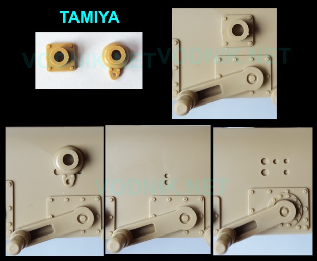
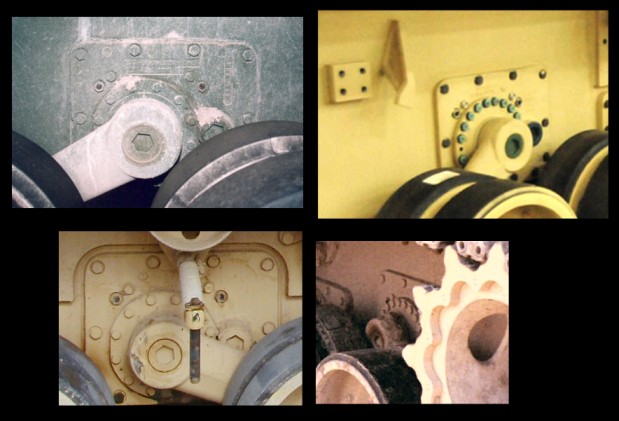
Tamiya kit still includes original parts from M1 kit to attach rollers - with square bases, but they are not meant to be used. I included them in a photo below anyway, to show how they hide the positioning holes in the hull tub walls. Tamiya also included new parts with rounded base. This shape is more accurate, but unfortunately it no longer covers the holes in the hull properly. One problem with Tamiya lower hull is that they did not represent thick extra armor plates that are located on both sides of the hull side walls. These plates are longer on the right side of the tank and shorter on the left. Three of four support rollers are attached on these additional plates, and only one - the rear left one - is attached directly to thinner hull side. As all rollers have to be at the same position relative to tracks, the mounting for this rear left roller is a bit different from the other three, slightly larger with more of the rounded base visible around the cylindrical socket for roller axle. Because there is no thicker armor represented in the Tamiya kit, all roller mountings are identical and the shape is closer to the larger left rear one in the real tank.
Tamiya also molded the mounting place for side skirt supports integrally with roller mountings - it isn't entirely accurate, as in reality there is a small space between these parts, but it is acceptable simplification.
In the center bottom of the image below is, as far as I was able to spot, the only difference between the old lower hull tub from M1 kit and this part in 35326 kit. Tamiya added two small holes above the torsion bar mounting plate for fourth road wheel. They are used to establish position of one of the side skirt supports. These supports were not included in earlier Tamiya M1, M1A1 and M1A2 kits. Now they are present, so Tamiya had to provide some aid to position them properly.
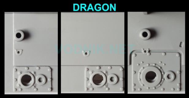
In the Dragon kit the mountings for rollers are very simplified - just simple cylinders protruding from the hull tub side. The left rear mounting is also a simple cylinder - just a bit longer than the other three. In the picture below you can also see small mounting plates for skirt supports molded on the hull surface. They appear to be a bit too small
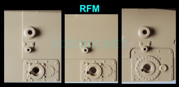
In the RFM kit the mountings are a bit more detailed and accurate. I don't show it in the picture, but the left rear mounting is a bit larger, as it should be. Mounting plates for skirt supports are significantly larger than they should be. Also note that there is a bolt missing in the lower right corner of the larger torsion bar mounting plates.
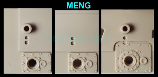
Meng roller mountings are just as simple as Dragon ones, except for the left rear one, which has correct curved base (not shown in the picture). Meng did not mold the side skirt support mounting plates on the hull - they are molded with supports, so here we only have positioning holes in the hull.
Academy parts look quite similar to the RFM ones, with well represented larger left rear roller mounting, but mounting plates for skirt supports are smaller - more accurate.
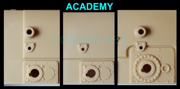
LOWER HULL TUB
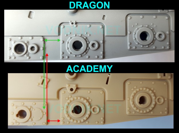
In the images above you can see that Dragon and Meng torsion bar mounting plates are quite different from those represented in RFM and Academy kits. Actually both are accurate. Dragon/Meng is an original earlier type with less bolts. RFM/Academy version is later reinforced version with more bolts on larger plates. Unfortunately I'm not sure when the new reinforced plates started to appear. I don't know if all M1A2 SEP tanks should have this type, or were they introduced during the SEP program and early ones could have the original plates. If the former is true, then the plates in Dragon and Meng kits would be inaccurate for M1A2 SEP variant. But without solid references I can't be sure. Photos below show both types of plates.
You can also notice that torsion bar mounting plates in the Tamiya kit are completely wrong...
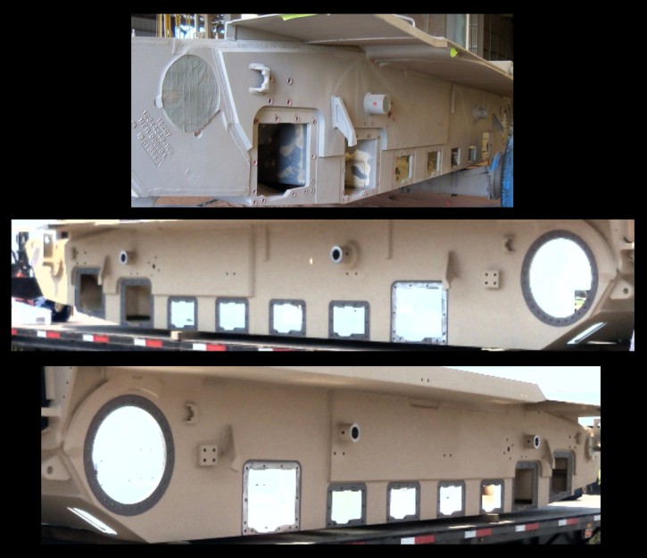
Photos below show the configuration of the real hull tub.
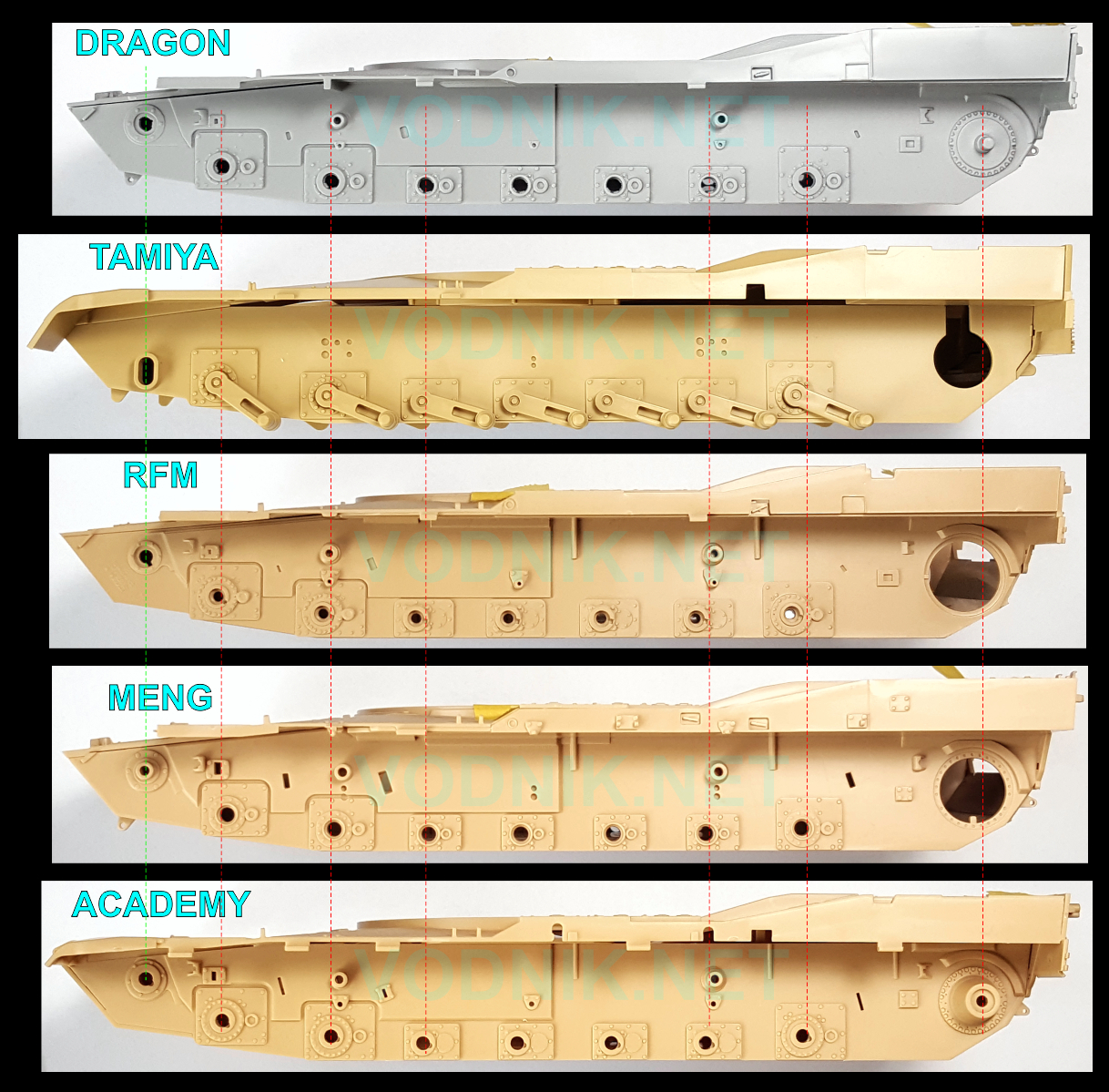
And now let's take a look at the hull tubs in kits. In the picture below the hull images are carefully scaled and aligned to the position of the idler arm axle.
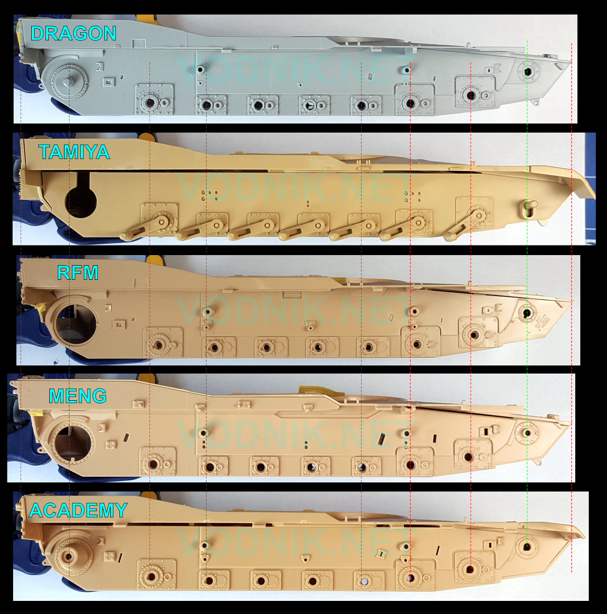
It is not visible in above photos, but with one exception all hull tubs are molded as a single piece. The exception is the Academy kit, in which the side walls are separate parts. The fit is very good however and Academy included very rigid bulkheads to put inside the hull, so the assembly is easy and there is no risk of misalignment or warping.
You can see that not only some of the torsion bar mounting plates in the Tamiya kit are wrong shape and size, the location of swing arms are all wrong... The hull "nose" also seems to be too long and the sprocket wheel is located way too far forward. And as I already mentioned earlier, there are no extra armor plates on hull sides. The hull tub sides are basically devoid of any details other than torsion bar plates.
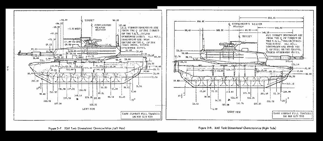
In the Dragon kit the geometry of suspension is accurate. I know, because it is based on dimensions shown in these XM1 drawings from the official source, and it has not changed since then:
But there are some details missing from the hull tub walls. There should be a trapezoid shaped cutout in the upper edge of armor on the right side, beneath the turret base - it is not present in the Dragon kit. Also missing are two vertical reinforcements on the left side of the hull tub.
The Meng kit seems to have the geometry very similar to that of Dragon kit, although it is just slightly "compressed" - just about two millimeters across the whole hull length. The hull tub itself is slightly longer than in other kits, but it isn't particularly big difference. The vertical reinforcements on the left side are present. There is also a trapezoid shaped cutout, but it is much too long. I think that Meng designer misinterpreted the weld line that extends forward from the cutout as an extension of the actual cutout. By the way: that weld line is not present in any of the kits.
The RFM hull is shortest of all and the suspension is noticeably "compressed". Note that with idler position aligned in this and the Dragon kit, the position of the last road wheel is about four - five millimeters further forward in RFM kit. The geometry of the RFM kit suspension - at least the general placement of the torsion bar mounting plates is worryingly similar to that in the Tamiya kit... Actually it is practically identical on the left side of the hull, what means it is equally inaccurate. At least vertical reinforcements on the left side of the hull are present. There is also a cutout on the right side, but it is rectangular, not trapezoidal, and it is too short.
Both Meng and RFM kits have some additional details on the left side of the hull - reinforcements along the top edge of the hull tub wall - that are missing from all other kits.
There is something slightly wrong with the Academy hull.
If you look closely on photos of the right side of the hull, you can see that the distance between the plates for second
and third wheels is noticeably shorter than in other three kits (also see image
below). This means that second and third road wheels will be too close to each
other after assembly, what has already been observed by other reviewers. But
positions of the last road wheel and sprocket are identical as in the Meng kit
and very close to that in Dragon kit. Interestingly the geometry on the left
side of the hull is fine. Correcting the error of distance between right 2nd and 3rd wheels is possible by cutting the
right hull wall (which luckily is
a separate PART) and adjusting the distances between wheels - filling the
resulting gaps with styrene strips. But it is a lot of work that shouldn't be
necessary in otherwise very nice kit. Also it will move right wheels from 3rd to 7th
to the rear what will in fact make the whole suspension a bit too stretched
lengthwise on this side. Hopefully it wouldn't be noticeable, unlike the existing error that
can be easily noticed.
The vertical reinforcements on the left side are
present, but the cutout on the right side is missing.
GO TO NEXT PAGE
PAGE 1
PAGE 2 PAGE
3 PAGE 5 PAGE 6
PAGE 7
![]()
![]()
![]()
Copyright © 2016 VODNIK, email: pawel.k at vodnik dot net