|
|
|
|

Accurizing and
detailing
the Tamiya M2A2 IFV kit.
Tamiya
1:35
PART
6
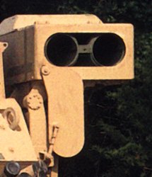
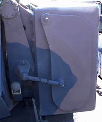
Gunner's sight has older style doors in Tamiya M2A2 kit, but it is perfectly OK for early M2A2. First vehicles with newer style doors (like those added to Tamiya M2A2ODS kit) were used in small number during Desert Storm and all vehicles have been retrofitted with them after the war. The only correction necessary to doors in the kit is separating left and right halves, as they are molded together. You may also wish to add support bars if you plan to attach doors open. There should be four small lifting eyes - one bolted to each corner of the gunner's sight (see one of the last pictures on previous page) - these are quite small in scale, but can be added if you wish. On the back of the gunner's sight you attach part A2. You should either drill holes in three styrene rods that make part A2 or replace them with some metal tubing, as these tubes are signal flag holders in reality and obviously are not solid.
On the left side of the turret is the antenna mount protected by the guard welded from solid steel bars. It is attached to the turret using two brackets - in Tamiya kit these brackets are missing and bars are attached directly to the turret. You can add these brackets from a piece of brass sheet (e.g. old PE fret). You should also replace the vertical bar that supports the guard as it is too thick in the kit (see photo below).
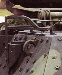 |
| Note
brackets that are used to attach antenna guard to the turret. Also note that the vertical bar is relatively thin. Photo VP |
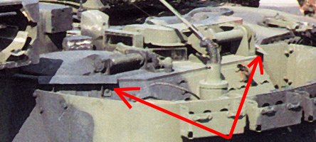
Around both gunner's and TC's hatches there are steel bars welded to the turret armor - similar to those around the hull cargo hatch and probably also limiting the amount of water that gets to open hatches during rain. You can see one of bars on some of the last photos on previous page, in front of commander's hatch, and my drawing below shows where all the bars are. Behind the TC's and gunner's hatch, on the rear side sloped armor plates, actually inside the bustle rack are two small metal "roofs" - rectangular sheets of metal attached to the armor with two brackets. I don't really know they function, but they are at least easy to add from thin styrene or metal sheet.
|
|
|
| Note
two metal plates ("roofs") attached to the turret sides inside
bustle rack. Note the metal shield over the TC's periscope between hatches. Photo VP |
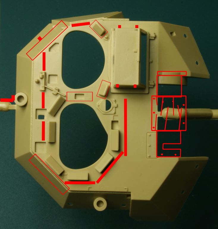
Positions
of various parts missing from the turret are marked in red. Thick red lines around hatches are steel bars welded to the armor. Click on the picture to enlarge it. |
Under the left "roof" there should be a large lifting eye attached, but it is not present in Tamiya kits.
On both sides of gunner's hatch there are his two small periscopes and to the left of his hatch is one bigger and higher (to see above gunner's hatch) TC's periscope (part A41). All three have metal shields / covers over them - missing from Tamiya M2A2 kits. Unlike covers on periscopes on the hull, these are not the same shape as periscopes - hey are more boxy with flat horizontal top plates. I suggest you add these covers from thin metal (brass or aluminum) sheet. Hatches themselves are fine, one small criticism being that the index wheel, which allows TC to set his hatch open in several fixed positions is molded as part of the hinge attached to the turret, while in fact it should be a part of the hatch and should move with it.
|
|
|
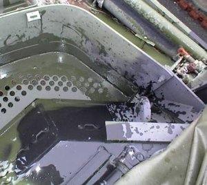
| Large
lifting eye is welded to the armor under the left "roof". On the bottom of the photo you can see one of the bars welded to the turret top armor around hatches. Note holes in the bottom plate of bustle rack. Photo RG |
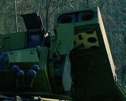
You
can see metal covers over three periscopes closest to the gunner's hatch (one TC's periscope and two gunner's own). Photo RG |
The shape of the bustle rack attached to the back of the turret is not quite accurate in Tamiya kit. Its left side should be more flat - you can see it on the photo above and on my drawing below. It is quite difficult to correct, unless you want to make the whole new bustle rack... Drill holes in the bottom of bustle rack (kit part C4), as Tamiya made this part solid. In the real Bradley there is a large bracket that holds the bustle rack to the turret - it is attached to the antenna mount column on the turret back plate. There should also be a lot of small tie-downs on this plate. There should also be small brackets attached to the bustle rack wall - two behind each ammo rack - they are used to attach straps that hold ammo cans in place (see photo below). Ammo racks and cans in the Tamiya kit look acceptably, but lack holding straps on ammo cans.
|
|
|
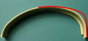
| Red
line shows more correct shape of bustle rack. It is just approximation
to show you where the problem is - do not consider my drawing to be a template. |
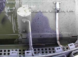
Note
large bracket connecting the antenna column to the bustle rack and numerous tie-downs on the turret armor. Also note brackets on the rack wall (bottom of the picture) used to strap ammo cans. Photo RG |
TOW LAUNCHER
The last part left to attach to the model is the TOW launcher. Unfortunately Tamiya used all parts from their old M2 kit, ignoring the fact that all Bradleys beginning with M2A1 and M3A1 variants use newer style launcher...
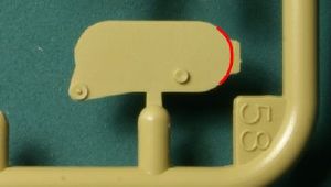
Launcher is attached on the left side of the turret using parts B56, B54, B55 and B45. Part B45 is a bit too small and has wrong shape - see photos below. Adding some cable connecting the launcher to the turret to these kit parts is also advisable.
|
|
|
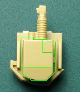
| Part B45 is too small. Green lines show more correct size and shape. | The real thing - note cables connecting the launcher to the turret. On the left is the photo of M2 Bradley part, on the right is M2A2 part. |
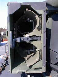
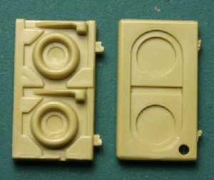
The bottom plate of the launcher box (part B53) is solid between the two molded-on brackets, with only round depressions molded on it. This shape is correct for old M2 Bradley launcher, but in M2A2 there is no solid plate between two supporting brackets - you can see what is inside the launcher box - unfortunately I was not able to find a single photo of the bottom of the M2A2 launcher box. I only have some pictures that clearly show that there is no solid plate there, just a hole. If you make this hole in part B53, you need to scratch build the interior of the launcher box and unfortunately I can't help here as I simply don't know how it looks. On the bottom of the launcher should be a small mushroom-shaped thing that is a part of locking mechanism that holds the launcher in place when in transport position.
|
|
|
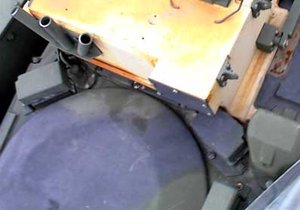
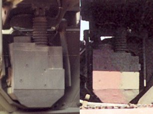
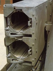
| You
can see the sky through the bottom of the launcher - there is definitely a large hole there. |
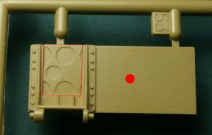
Remove
the part in red rectangle. Red dot shows where the mushroom-shaped part of the launcher locking mechanism should be. |
The front of the launcher
in Tamiya kit looks fine, but only for the old M2/M3 Bradley launcher. There are
no holes in this part, but it is correct for a loaded launcher, as missile tubes
have flat (paper?) covers on both ends. Unfortunately part B57 looks nothing
like the front of newer launcher installed on all M2A2 Bradleys - see photos
below. If you choose to build launcher in your model in firing position, you
have to scratch build the new launcher front. The back side of the launcher is
not much better in the kit either. Tamiya part B60 is highly simplified replica
of a part from early M2/M3 Bradley, with two separate unloading handles, one for
each tube. Again the kit part looks like it is loaded with missiles, as ends of
missile tubes are molded-in. Newer launchers installed in M2A2 vehicles have
modified unloading mechanism with just one bigger handle in the middle - see
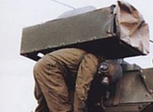
photos below. You can scratch build new back of the launcher, or cover the kit
part with canvas cover, as on the photo above, to avoid scratch building - these
covers are very common on Bradleys, being removed only when the launcher is
loaded.
The hinged front cover of the launcher in the kit has a shape typical for old M2
Bradleys, but on M2A2s slightly different cover is installed. It has
smoother oval outline, without the rectangular protrusion on one side.
Installing the kit part is not completely wrong idea however, as VERY rarely
newer M2A2s can be seen with old style covers. Among a few hundred photos of
Bradleys I have, there are just two showing M2A2s with old style cover
installed. And modification of the kit part to new style shape is very easy, so
I suggest you just do it. The moveable cover should be attached to the kit part
B54 with a small actuating arm, missing from the kit. It is easy to add from a
piece of styrene rod. You may also add a mushroom-shaped button that should be
located near the actuating arm joint on part B54 (see photo). On both side walls
of the launcher box (they are side walls in firing position, or top and bottom
wall in transport position) there should be a line of seven bolt heads on each
side, along the bottom edge of the wall. These bolts are not present at all in
Tamiya part. In older M2 type launcher these bolt heads were hidden in small
hollows drilled in the side plate wall and flush with the wall. Luckily in newer
launcher installed in M2A2 vehicles those bolt heads are no longer flush with
the metal plate, as there are no hollows in the plate anymore - bolts just stick
out of it, what makes them easier to add to the model part.
|
|
|
| Old type of launcher on M2 Bradley. | The
back of the old launcher on M2 Bradley. Note two separate unloading handles. Also note how the launcher box is latched to the turret. Photo VP |
|
|
|
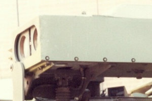
| Front
of the newer type of launcher, installed in A1 and A2 variants of Bradleys. |
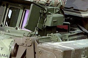
The
back of the newer type of launcher with just one unloading handle. Photo RG |
|
|
|
| There
is a line of bolts on both sides of the launcher. This is old type of launcher on M2 Bradley and bolt heads were flush with the side of the launcher. |
In
M2A2 launcher bolt heads are no longer flush with the wall of the launcher box - they stick out. But this makes them easier to add to the model part. |
|
|
|
| Front
and back of the launcher in all Tamiya Bradley kits. These parts look similar to parts of old M2 Bradley on photos above. |
Modification of the shape of part B58 should be easy. |
 |
|
| Front
of the launcher on M2A2 Bradley in transport position. Note details of actuating rod and a mushroom-shaped button next to it. Photo RG |
|
FINAL TOUCHES
One last thing missing from armor plates of Tamiya Bradley models are non-slip surfaces. On real Bradleys the non-slip compound is only applied to hull surfaces, not to the turret (at least not on pre-ODS vehicles). To identify areas where the non-slip surfaces are applied just look at various photos, including some in this article, as I do not have any "official pattern" drawings. To add non-slip surfaces to your model you may use the same method I used in my Bradley - >read about it here<.
CONCLUSION
Well, if you managed to read through my article and get to this point, I can only congratulate you! I hope you were able to understand something from what I wrote and that you will be able to use some of the information included in this article in your next M2A2 Bradley model project. As you had a chance to find out yourself now, the Tamiya kit is not exactly the most accurate model ever created. But sadly it is the only model of this vehicle on the market - all others are just very poor copies of it (e.g. Lee Models and Hobbycraft). Tamiya kit is a pleasure to build out of the box with all parts fitting just perfectly, but for modelers striving for accuracy it presents a lot of scratch building opportunities, as without the extra effort the model just roughly resembles the real thing as far as any details are concerned. Luckily most problems of this kit are missing parts and what you get in the kit is almost always correct. It is always easier to just add missing details than perform a major surgery to existing kit parts - and luckily no such surgery is really necessary to improve the accuracy of this kit.
Happy modeling!
You can see results of most of described above changes in my M3A2 Bradley model >here< .
GO
TO PREVIOUS PAGE
GO TO ODS SUPPLEMENT
PART1 PART2
PART3 PART4
PART5 PART6
SUPPLEMENT
|
Most of the photos of real vehicles in this article came from various sources on the Internet. I have so many of them downloaded on my computer that I lost track of where each of them came from. If you recognized some of the pictures as yours and want me to credit you for them here, or you want me to remove them, let me know - I'll sure do it. |
![]()
![]()
![]()
Copyright © 2004 VODNIK, mailto:pawel@vodnik.net