|
|
|
|
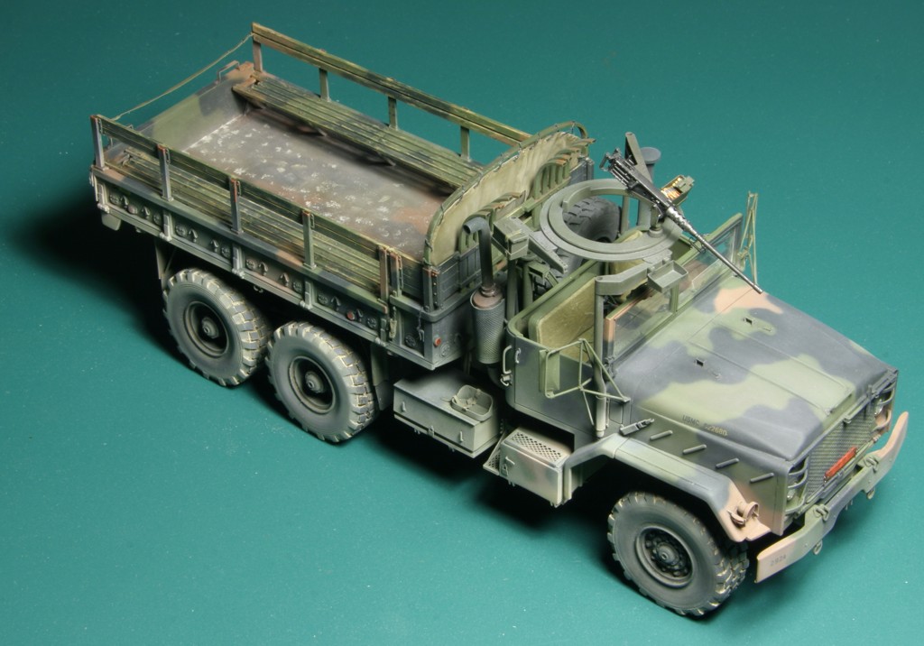
Superdetailing
the M923A1
truck
Italeri
1:35
PART 1
In this article I will describe step by step all the modifications I made to my model of M923A1 truck. I will use the sequence of assembly as suggested in kit's instructions, although my own model was built in much more chaotic way - it was the result of this project being a complete rebuild of almost finished model.
STEP 1
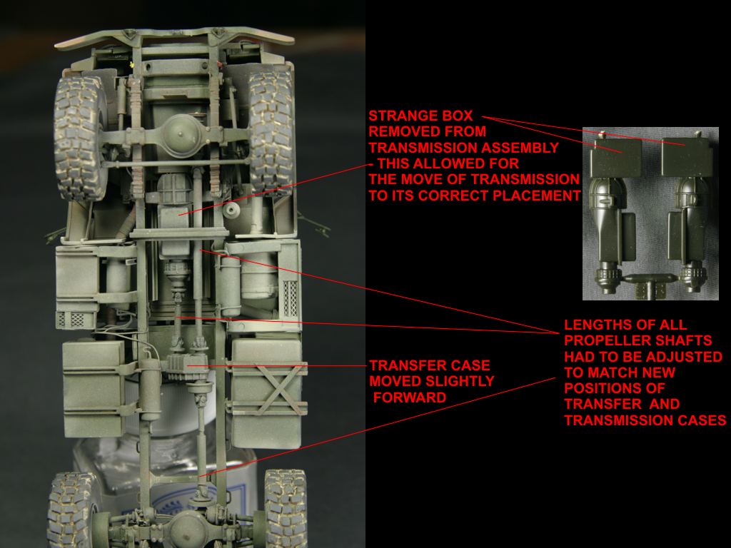
Italeri suggest to start model construction with the suspension frame assembly. First part to put together are transmission and transfer case. The former (parts 11B and 12 B) has some strange blocky shape molded on front of it - remove it completely, as it should not be there and it makes the whole transmission assembly to fit to far aft on the model.
Main frame parts 1A and 14A require some work. As the transmission and transfer
case will be attached in different positions than Italeri planned, I suggest
removing the small locating "frames" for these parts from the inner
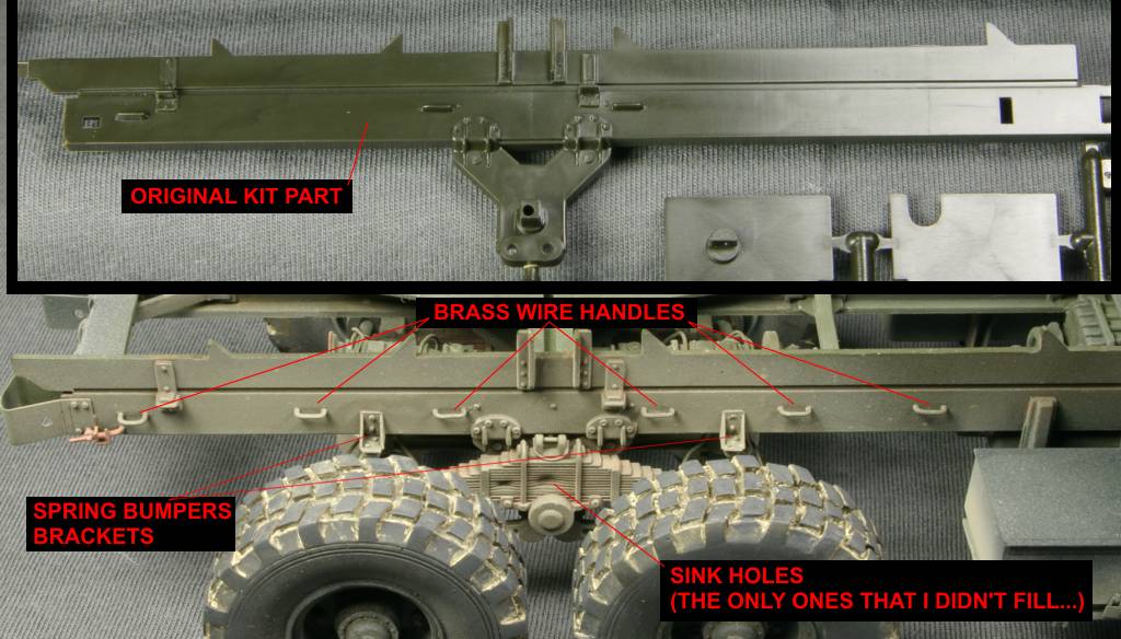
side of frame. There should be several handles on outer sides of frame, some are
completely missing from the kit and others are molded on as rectangular stabs -
I added these using brass wire.
Frame member 7A is too narrow in the kit - I widened it using pieces of styrene
sheet and then attached a PE part from Eduard set (35511) to it. I was not able
to determine correct shape of this member so it is not exactly accurate in my
model, but closer to reality than the kit part.
I suggest assembling all the parts in step 1. except for the transfer case,
transmission and part 13A now. It is necessary to make sure all parts are
correctly aligned. Once the frame is complete and glue has fully dried it is
time to attach the transmission. I suggest you dry fit the cab floor now,
possibly attaching it with a piece of masking tape to the suspension frame. Now
you can attach the transmission to the frame in such a way that front of
transmission touches the vertical part of "engine" shape on the
underside of the cab. Do not glue the transmission to the cab floor yet!!! Glue
it only to the frame, making sure it is parallel to it's sides. It is best to
leave the cab floor attached to the frame until the glue has settled completely
on transmission to make sure it stays at the right place. You can now glue the
transfer case to the frame. Move it a few millimeters forward from the position
suggested by Italeri (see my photos). Now you have to modify the length of part
13A to make it fit between transfer case and transmission. I suggest cutting the
middle section from it completely and gluing the two cardan joints separately to
transfer case and transmission and then glue the piece of styrene rod cut to
matching length between them.
|
|
|
STEP 2
In this step you assemble all three axles. You can build them as suggested - I only added Eduard PE discs to both parts 17B and then added styrene bolt heads in the middle of them.
STEP 3
Attach both leaf springs to the frame. There are nasty sink holes on sides of
springs - they are not easy to fill, but you can try if you wish. Once springs
are attached you may add scratch built inner mounting plates to them - only
outer plates are molded on frame sides. Once you attach the front axle you need
to modify the length of the drive shaft 27B. As we moved the transfer case
forward, the shaft is now too long, so you need to cut the slice out of it to
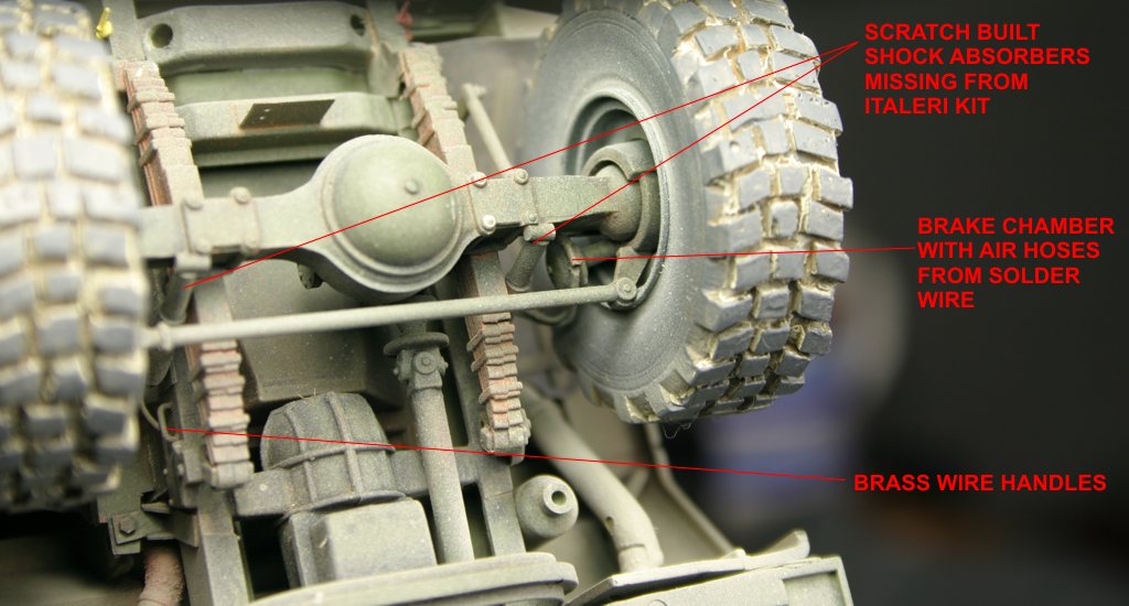
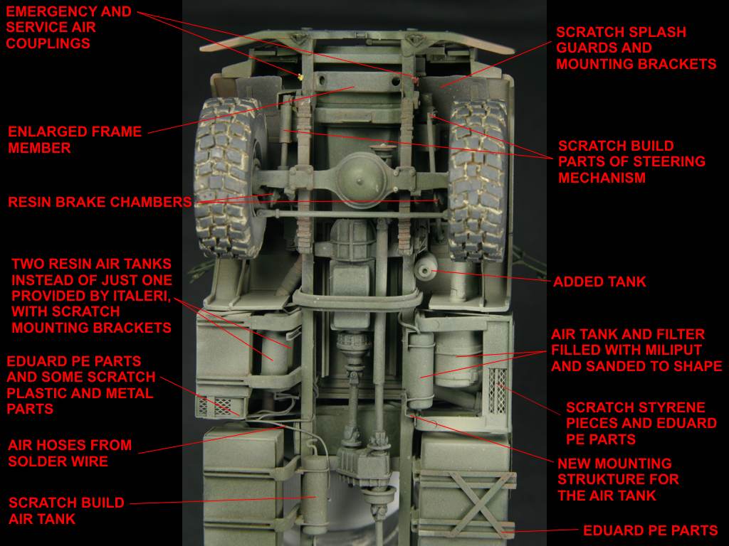
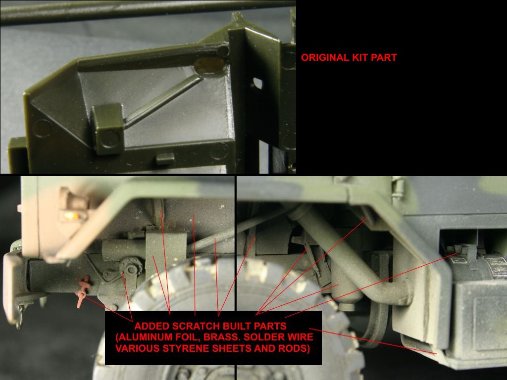
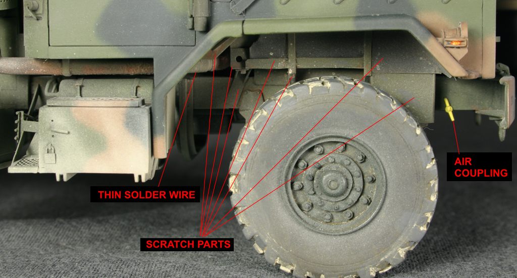
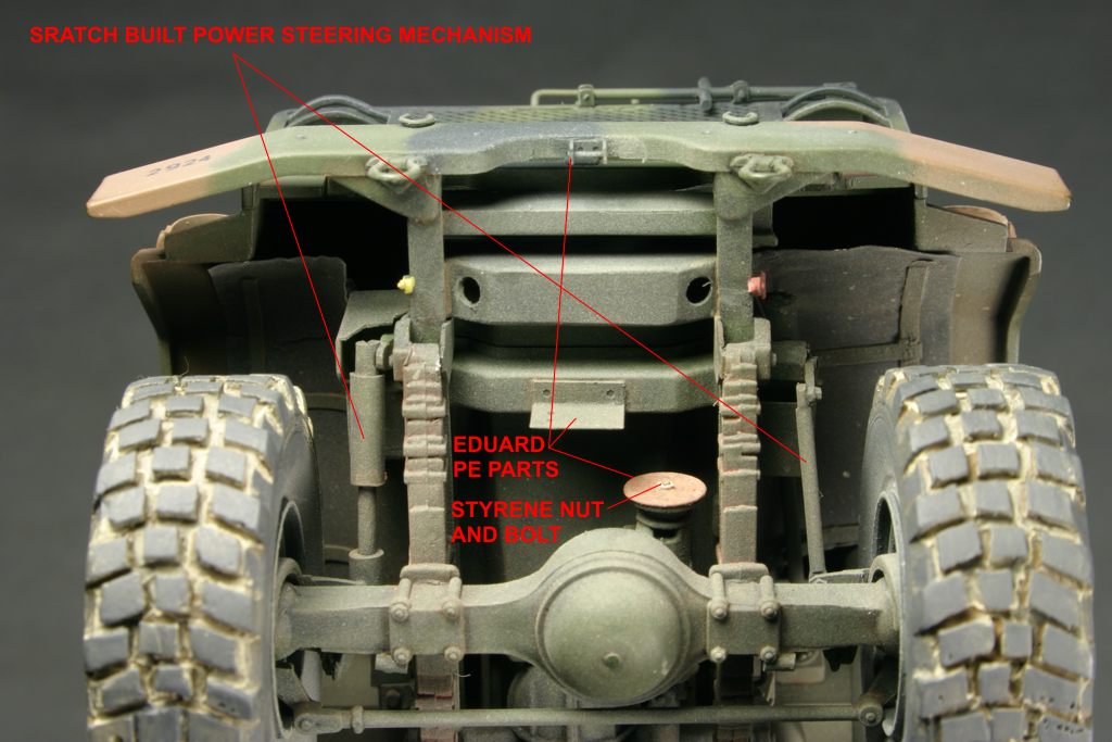
make it fit correctly. Italeri missed a few important parts around the front
axle. Using various pieces of styrene rods and sheets I added two shock
absorbers and complete power steering mechanism - see photos. I also added two
brake chambers (from resin Real Model set, see review >here<)
and associated plumbing (solder wire). I added a tank scratch built from styrene
rod attached vertically to the suspension frame behind the left wheel - I don't
know what it is, but it is quite visible on photos of the real truck and missed
completely by Italeri.
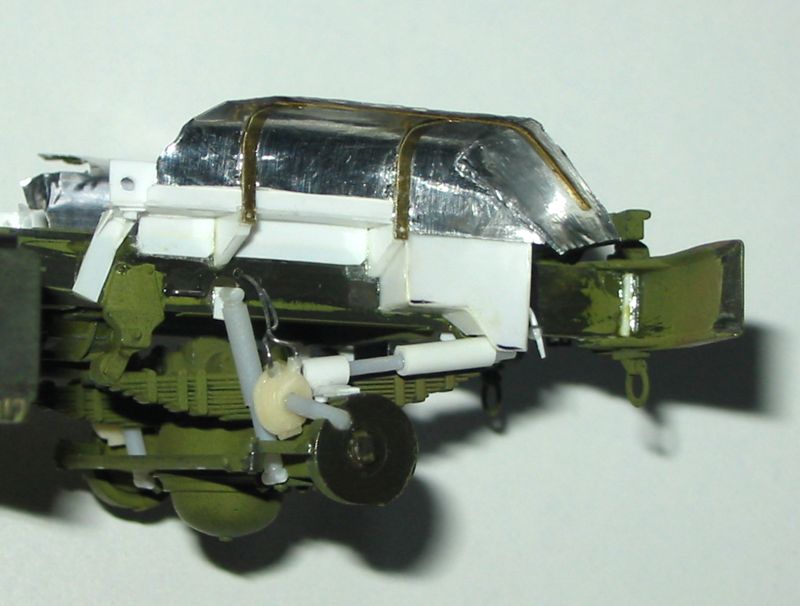
I did not install the air tank 24A at this stage as it should not be attached directly
to the frame, but to the part 42A. I suggest you fill the tank with
Milliput now to give it full shape and remove all mounting brackets from it to
prepare it for installation later using new, scratch built brackets.
|
|
|
|
|
|
|
|
|
|
|
|
Copyright © 2003 VODNIK, mailto:pawel@vodnik.net