![]()
Building Academy MiG-29A
Page 2
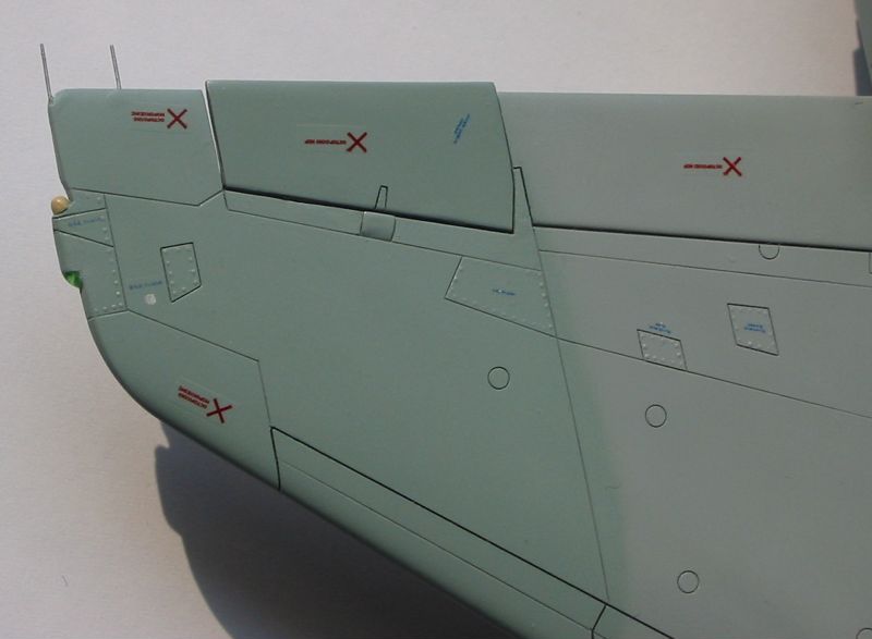
I put the nose section aside and turned my attention to the main fuselage section. I replaced big panel with vents on the bottom part of fuselage with the PE part from Eduard. I also cut the opening for the APU exhaust just next to mentioned vents. I glued a small styrene plate on the inside of fuselage to close the APU exhaust - it will be painted black later to give the impression of depth. I also drilled three oval openings (drains?) on each engine nacelle. As there are very characteristic panel lines on engine nacelles of a real plane that were missing on the model, I scribed a few new lines to represent them. I also removed a couple of panel lines, that should not be there, from each nacelle using gap filling superglue. I removed parts of engine exhaust nozzle shields that were molded as parts of upper fuselage - I replaced them later with PE parts from Part set.
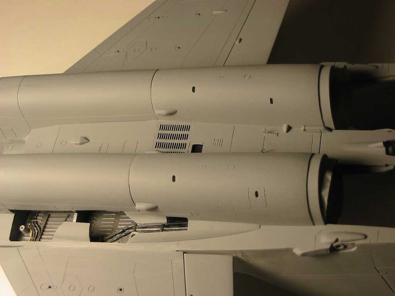 |
On
this picture you can see holes drilled in engine nacelles and some
rescribed panel lines there. Note the large panel with vents taken from
photoetched Eduard set. You may also spot some other small brass and plastic
details added later in this area. |
As I mentioned in my review of the kit, the main gear wells are very inaccurate both inside and out, but I decided that correcting these parts would be too much hassle. As I chose not to correct them, I also decided not to add any details inside. They will not look correct anyway, so who cares... I just glued gear well walls in place.
 |
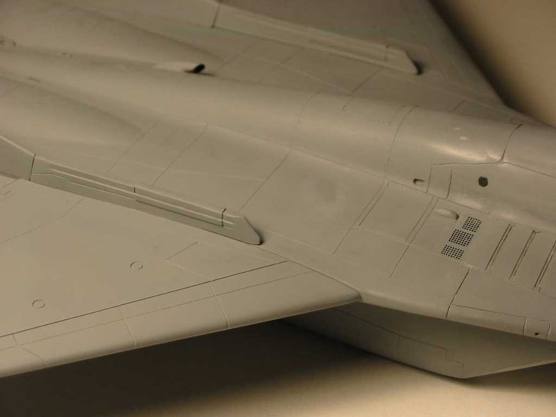
Here
you can see the shape of the main gear well of the model. |
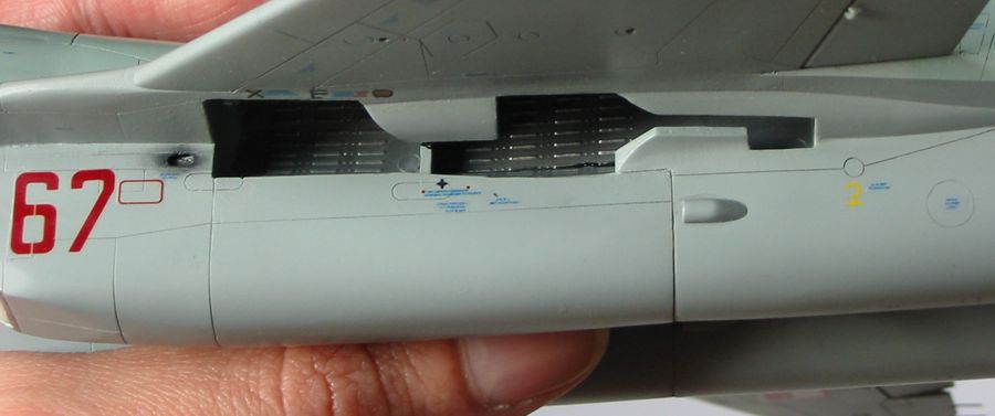
In the upper part of the fuselage I made oval openings on both sides of the dorsal spine and also drilled one larger round hole for the inspection window on starboard side of the spine. I used a slice of clear sprue, painted black on the inside, to close the window. I also replaced two panels right behind the upper auxiliary engine air intakes with PE parts.
After all these modifications of main fuselage parts were finished I glued these parts together.
Unfortunately I made a mistake that cost me a lot of work. Now I know that it was not good idea to assemble the fuselage in order described above. I should have glued upper front and rear fuselage sections together, do the same with bottom sections, and only later glue these two fuselage halves together. When I started to glue the completed front and rear sections of fuselage together I realized how bad the fit is. I had to insert a piece of plastic vertically to the inside of the rear section to force the glued halves to spread wider. I had to repeat the same trick with two smaller pieces of plastic on both sides of forward fuselage section, near the upper air intakes. These modifications changed the profile of both fuselage section enough to improve the fit. I glued these parts together but a lot of filler was still needed to make the joint line smooth. I was not fully successful - if you carefully watch the pictures in the gallery you will notice that bottom line of port side LERX's leading edge is not quite straight.
Next I started to assemble engine air intakes. I quickly decided that I need to close them, as there are no ducts inside, and many ejector pin marks to remove. There are to options to close intakes: one is to scratchbuild the external intake covers, and the other is to install the supersonic shock ramps (FOD screens) in fully closed position. I chose the latter option, as I had nice PE screens to replace kits screens, and it is not unusual to see parked airplane with both the FOD screens and the upper auxiliary air intakes closed. I drilled oval openings on outer side of each intake, just ahead of main landing gear wells. It was actually a mistake as there should be such opening only on the portside intake, but I realized that after finishing the model... Assembled intakes don't fit to the fuselage very well. The fit is good on the inner side of the intake, around the nose landing gear well, but on the outer side it is much worse. I added strips of styrene in several places to the edge of each intake to improve fit, but some filler was needed anyway. I think that bad fit in this area was caused by previous problems with fit of nose and aft sections of fuselage - the joint line of these sections runs in the middle of the intakes. Probably if I would assemble nose and aft bottom fuselage parts together first, before attaching upper parts, the fit of intakes would also be much improved. The fit of the intakes to the engine nacelles could also be better. I corrected it a bit with some sanding, but it is still not perfect in my model.
Now that I had the fuselage in one part I started to rescribe panel lines. During the demolition phase that started my second attempt to build the Academy kit and during subsequent assembly that required a lot of filling and sanding, most of panel lines on the nose section of fuselage was lost. As I had to do scribing anyway I decided to modify at least some of the lines to their correct shapes. I used gap filling superglue to remove remaining incorrect panel lines on airplane's nose and cockpit area and then rescribed new lines there. Particularly important was correcting the shape of two big triangular antennae covers that are on each LERX. They were too small in Academy kit. Most rivets in the nose area were lost, but I decided that I can live without them. Other lines, like those on wings, stabilizers, top and bottom of the fuselage though not correct in many places were left intact. I also spared all the rivets that survived initial nose area sanding.
Next I installed tail fins. But first I improved them a bit. They don't have quite correct shape but it can't be corrected easily so I decided to accept it. They look OK, and as long as you don't try to compare them with scale plans of the prototype you will not notice a problem. I only added some details - I cut off the molded on position light on the port fin, to replace it later with a drop of Microscale Kristal Kleer. I added two small antennae to both sides of the fairing on port fin. I drilled a hole in the back of the fairing on the starboard fin to install anchor-shaped antenna (from PE Eduard set) later. I also used razor saw to cut small crevices over and under the rudders to make them look like separate parts. There are no lower ruder hinges in Academy kit, so I added them using some filler and tip of the compass needle (as a scriber tool). I also modified the areas of horizontal stabilizer attachment points to make them look more like on the prototype - it required some changes to lower part of each fin and the corresponding parts of the fuselage. I added pieces of styrene tubing as "sockets" for stabilizers, and glued them a little bit more forward than the Academy made their attachment holes (click here to see the picture where these modifications are well visible).
Fins fit quite well to the fuselage at correct angle, but some filler was necessary anyway to completely hide joint line around horizontal stabilizers.

All
added details on tail fins are visible on this picture of finished model.
Click on the photo to see enlarged version.
Wings and horizontal stabilizers
I could start to work on wings now. After drilling the holes for pylons in lower wing half, I glued both wing halves together. I thinned the trailing edges of whole wings with sandpaper. Then I used the razor saw to cut both sides of ailerons from wings. I also used panel line scriber to deepen the hinge lines of ailerons. After doing this I was able to raise the ailerons slightly to set them at an angle, at which they usually are on airplane that has its hydraulic systems turned off. Next I turned my attention to wingtips.
In the Academy kit this part of the wing is very simplified. It was quite easy to correct using the knife, some filler, new RHAW antenna from a piece of styrene rod and a position light made from a drop of Microscale Kristal Kleer painted with Humbrol clear paint (red and green). Unfortunately I don't have a picture of the original wing tip as Academy made it, so below is my drawing that shows the "before" and "after" views.
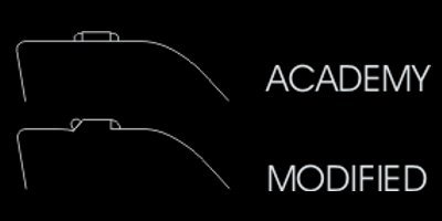
New
wingtip with navigation light made with Microscale Kristal Kleer.
Note added static dischargers and raised aileron (hardly noticeable on this
picture).
Click on the photo to see enlarged version.
Next I attached wings to the fuselage. The fit is very good on the top side of the wings, but it requires some filler on the bottom. Wings fit with correct anhedral, so no trimming is necessary to achieve this. When the wings were attached to the fuselage I added static dischargers. I used a thin steel wire to replicate them. I installed these wires by drilling the small holes in trailing edges of wings. It was not easy as the edges were already thinned and I had to cut small notch with the knife first and then insert 0,3 mm drilling bit to this notch and drill the hole. After drilling all holes I glued the pieces of wire with superglue. I made two mistakes - first was the way I installed these static dischargers. I made my life more complicated here, as these dischargers are actually installed in small fairings attached over and under the trailing edge of the wing on real aircraft - it would be much easier to add my dischargers the same way... The second mistake was to attach dischargers at these moment - I broke some of them off several times in later stages of model build. I also managed to stab my finger with one of them - don't try it yourself, it HURTS!
Horizontal stabilizers are correct shape and don't require much work. I only had to add new attachment points/pivots from styrene rod, as the old ones were damaged when I disassembled partially completed kit and they didn't fit to modified fuselage sockets anyway. I added static dischargers the same way I did it on wings. I also added them to previously installed tail fins. Stabilizers were left aside, not attached to the fuselage until the final steps of model assembly.
With wings and tail fins in place I was able to add fin root extensions that house flare/chaff dispensers. Most pictures of Polish MiG-29's show that they usually fly with covers mounted on dispensers. Replicating these covers was very easy - I simply glued pieces of styrene beams cut to size instead of original kit parts B11/12. Fin extension parts fit very well to wings/fuselage (they cover the wing joint line), but they don't fit well to the fin root. I twisted these parts a bit and this way managed to achieve almost perfect fit.
 |
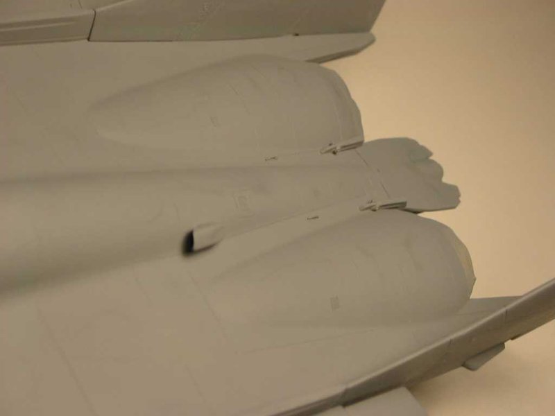
Flare
dispensers covered. You can also see the new shape of APU air intake
scoop - more on that later. Also note the round inspection window on
dorsal spine and added oval hole left of it. The panel below the
inspection window is form the Eduard PE set. |
With all the main airframe parts assembled I proceeded to adding some details.
First part added was the APU air intake scoop located at the back of dorsal
spine. I filed it to the right shape and opened the face of it with the drill
and a tip of the knife. Then I attached the airbrake in closed position. I
modified the upper airbrake hinges that were much to thick for the scale - I
used two extra parts that I found on sprues of this kit (E9) that were similar
in shape to the airbrake hinges, just thinner - I don't even know what they were
as they are mentioned in instructions as "un necessary". But with some trimming
and with small pieces of styrene added as front fairings, they fitted
perfectly. Lower hinges were acceptable. Some small photoetched details were
added to the upper and lower aft fuselage parts. Some are visible on the picture
below, and others on the picture >here<.
On the second picture you may also notice following details added:
- small scratchbuilt fairings near the lower airbrake hinges - these cover the
engine attachment points in real aircraft
- small PE hooks
- scratchbuilt cover of fuel tank attachment point
- small air intake scoops located on each side of engine nacelles - these were
kit parts, I only opened their faces with a knife and small round file.
 |
Modified
airbrake hinges and APU air intake scoop. Also note small PE lifting
eyes. |
At this point the model was basically ready for painting. Below I will describe how some subassemblies like landing gear, weapons, engine nozzles and others were prepared. Actually they were built in parallel with the other construction steps described above, but it is easier to write about them now.
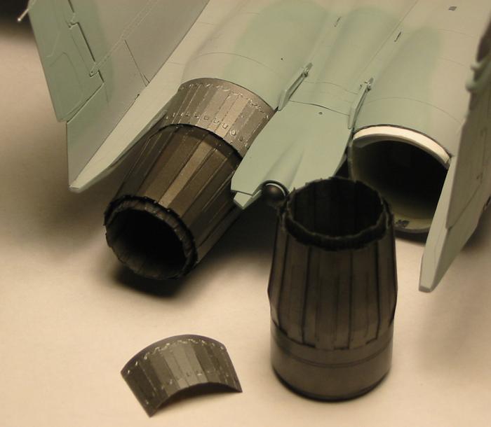
Original Academy exhaust nozzles have almost correct general size and shape,
but they are not detailed and the edge of turkey feathers is much too thick. As
I mentioned before I've bought exhaust nozzle photoetched set for MiG-29 from
Part (actually two of them as you only get one nozzle in one set). Building the
nozzle from this set is not the task for beginners. It is really difficult and
time consuming job, requires a lot of precision, patience and a very good super
glue. In the future I will rather look for quality resin sets...
The result is however very good. I think nozzles made from
Part set are a tiny bit too long. It could be corrected by installing them a bit
deeper in the original kit plastic part, but I noticed this problem too late to
do it. Fortunately the difference is not significant and new nozzles look
really cool! :-)
I painted inside of the nozzles white (ceramic coating) and then used black and brown pastels to give it natural burned appearance and sealed with Testors Dullcote. PE afterburner spray ring was painted with Testor's Aluminum Plate metalizer. On the first picture below outer surfaces are only primed and on the second they are already painted with Testor's Exhaust and Burnt Metal metalizers. They were also weathered with the black pastel dust on the outside. Nozzles were covered with Testor's Metalizer Sealer on the outside. There are also photoetched nozzle covers in the Part set that need to be attached to the upper fuselage in place of plastic parts - I assembled them and painted with Alclad II Dark Aluminum metalizer. Nozzles and covers were not attached to the fuselage at these point yet. I only attached a two strips of styrene to the fuselage to make installation of nozzle covers easier at later stage (one white styrene strip is clearly visible on one of the pictures below).
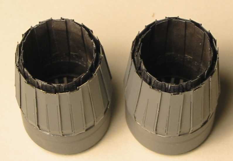 |
Photoetched
exhaust nozzles. Completely painted on the inside already, but just
primed on the outside. |
|
|
Finished
exhaust nozzles and covers. Left set is just test fitted to the model. |
![]()
![]()
Copyright © 2003 VODNIK, mailto:pawel@vodnik.net