|
|
|
|
Superdetailing
the M923A1
truck
PART 4
STEP 9
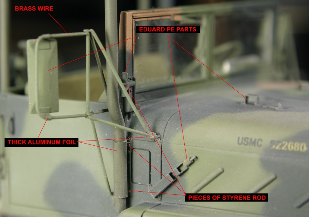
I did not install the warning light parts 105C and 106D. I replaced handles 92B with brass wire. I removed the mounting brackets from the air intake duct and replace them with scratch built parts from aluminum foil. I also added a section (from sprue) to the end of the duct to attach it to the back of air filter (part 91A).
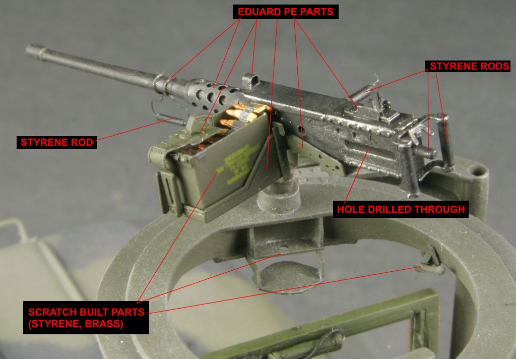
I scratch built new mounting brackets for weapons station poles. I added the mounting plates and some other details to the gun mount ring. I replaced ammo box trays with PE parts. I improved the M2HB machine gun with parts from Eduard PE set.
|
|
|
|
|
|
STEP 10
I replaced all parts attached to the cargo bed floor with PE parts from Eduard set. But before you do this I suggest you build a complete cargo bed (step 11), as PE parts can easily be damaged in the process.
STEP 11
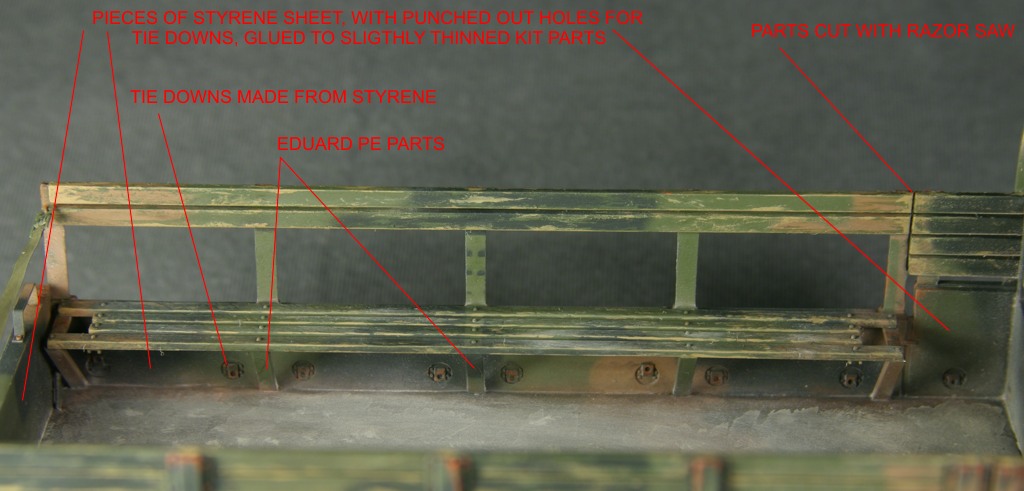
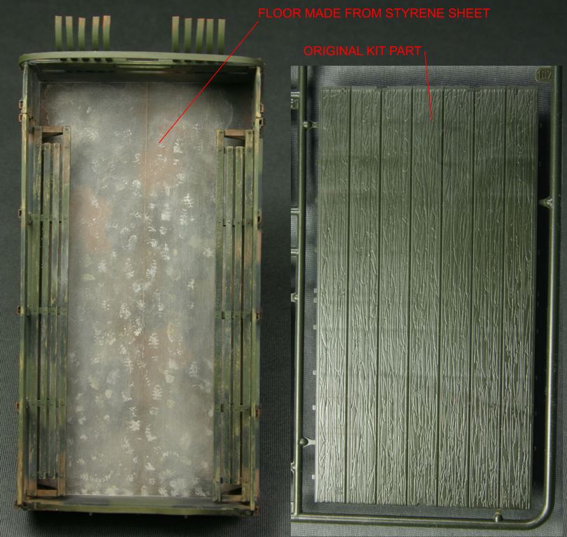
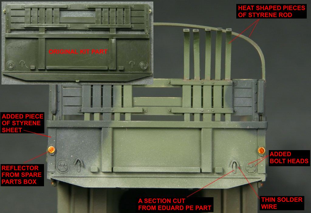
Cargo bed floor should be made of two flat plates welded along the middle of the floor. I sanded the wood texture of the floor part and glued thin styrene sheet over it.
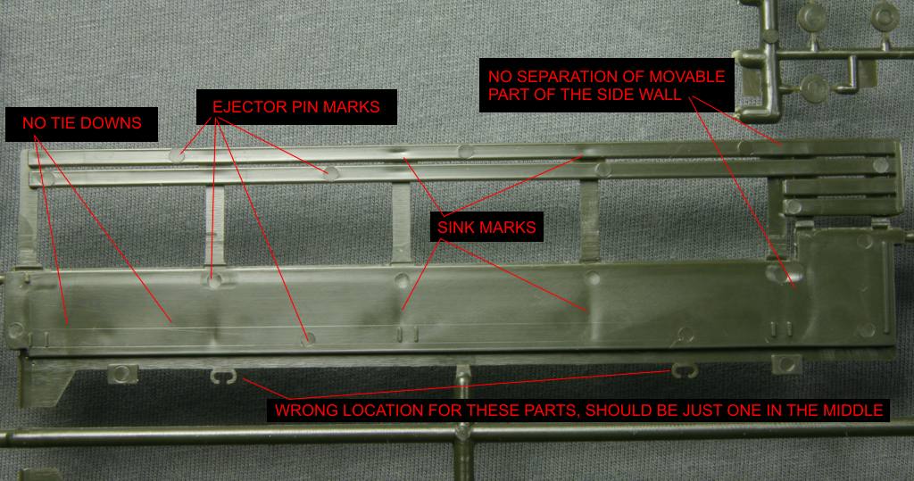
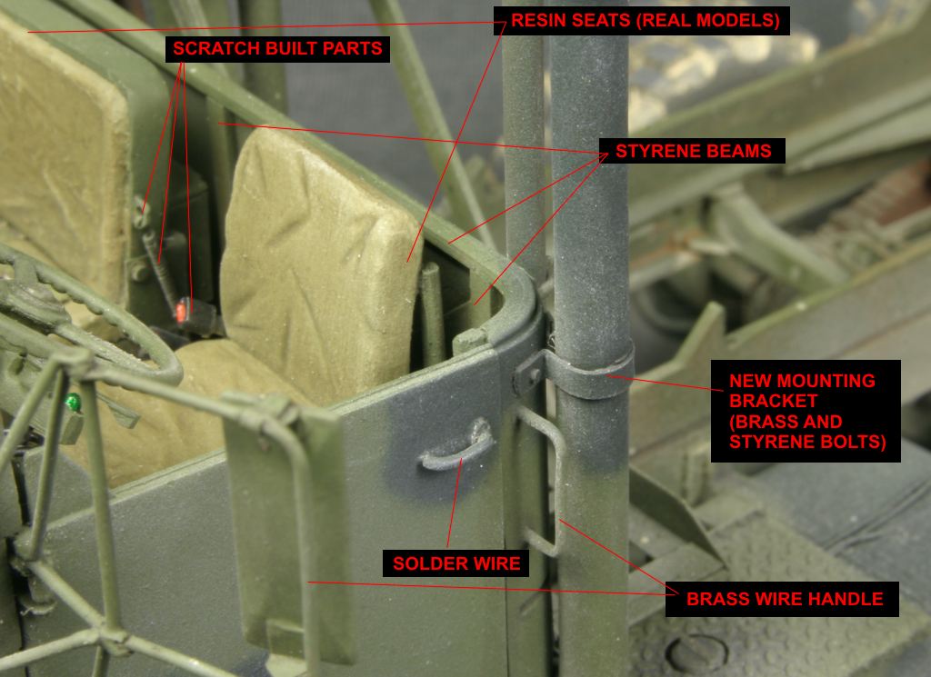
All side walls have sink holes and ejector pin marks on them so they have to be filled and sanded. I thinned all walls by about 0.3 mm and then glued the styrene sheets of the same thickness over them, but first I punched holes for tie downs in them. I scratch built tie downs from styrene. I replaced parts 115B with styrene rod. I added troop seats legs from Eduard PE set.
|
|
|
I removed molded on canvas hooks on all bed sides and replaced them with pieces of PE and solder wire. I added bolt heads to the small round covers (tie down mounts).
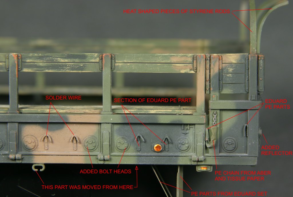
I used Eduard PE parts and Microscale Kristal Klear for tail lamps. I replaced handles/steps on rear gate with brass parts, added two small styrene bumpers and scratch built new gate hinges.
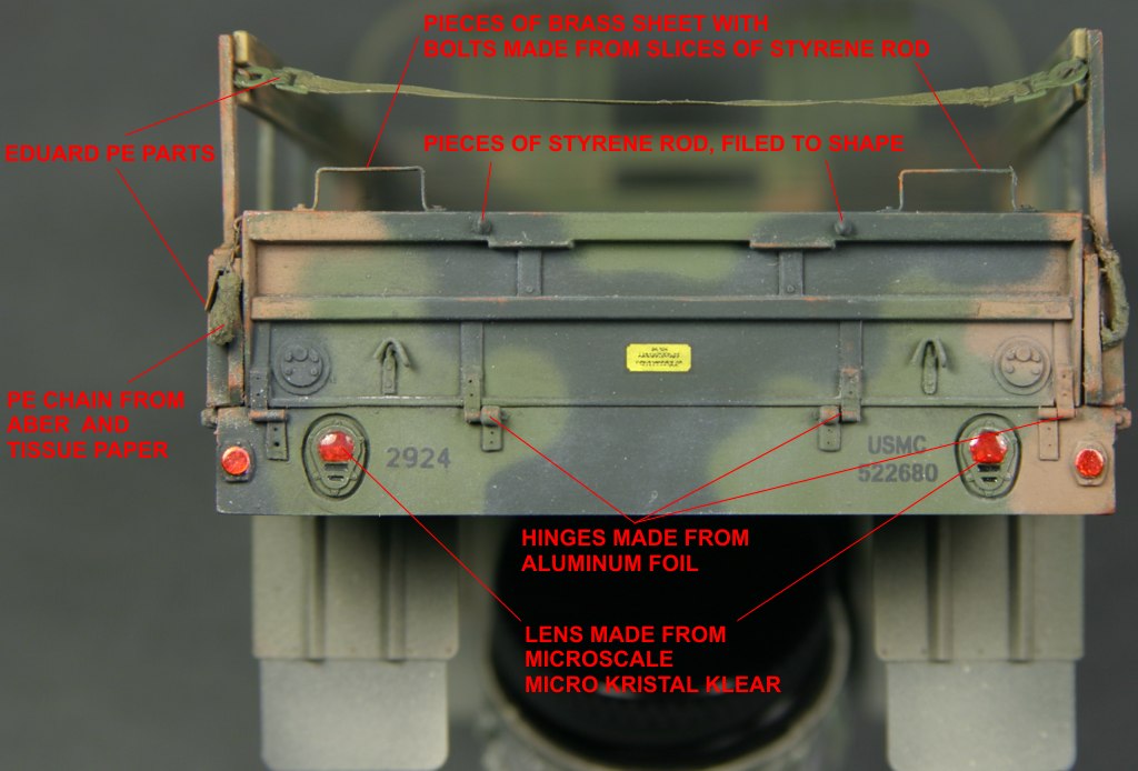
I added PE chains (from Aber) wrapped with white glue soaked tissue paper to cargo bed walls. I also added two round reflectors on front cargo bed wall missing from Italeri kit.
STEP 12
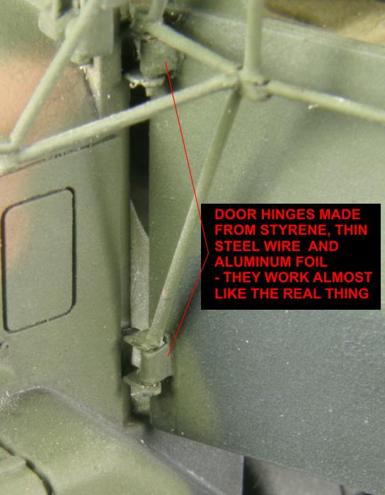
I removed window frames from both doors and did not install "glass"
parts. I added new handles to doors - some from Eduard PE set and some from
solder wire. I added workable hinges to the driver's door.
I scratch built new mirror frames from brass wires and used mirrors from Eduard
PE set instead of kit parts.
|
|
|
STEP 13
This is the step where you should put all the subassemblies together. I did not install the canvas cover to my model. Instead I made a single support bow from styrene rod and hanged a front curtain part of canvas cover (made from aluminum foil) on it. All other bows are in stored position behind the cab and on the cargo bed floor.
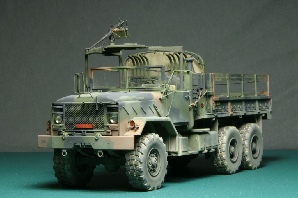
I added some other details not mentioned in the text - you can easily spot them on my photos, so study them carefully. Photos of my completed model are also in the gallery >here<.
References:
- US Army Technical Manuals: TM 9-2320-272-24P-1, TM 9-2320-272-24P-2, TM 9-2320-272-10, TM 9-2320-272-24-1, TM 9-2320-272-24-2, TM 9-2320-272-24-3, TM 9-2320-272-24-4
- "US Army 5-ton Truck M939 Series" Petr Brojo, Jan Mostek; Army Wheels in Detail Photo Manual, Capricorn Publications
- "U.S. Military Wheeled Vehicles" Michael Green, Greg Stewart; Concord Publications
- Rob Gronovius' "Motorpool" gallery on Armorama: http://www.armorama.com/motorpool
- "Heavy Trucks" gallery on Armorama: http://www.armorama.com/modules.php?set_albumName=albup95&op=modload&name=gallery&file=index&include=view_album.php
- various other Internet sites.
![]()
![]()
![]()
Copyright © 2003 VODNIK, mailto:pawel@vodnik.net