|
|
|
|

Accurizing and
detailing
the Tamiya M2A2 IFV kit.
Tamiya
1:35
PART
3
UPPER HULL
Tamiya
molded the upper hull as one large part C7 to which additional armor plates and
other details are attached. I will start with the details of the front armor
plate and move to the back of the vehicle describing all parts along the way.
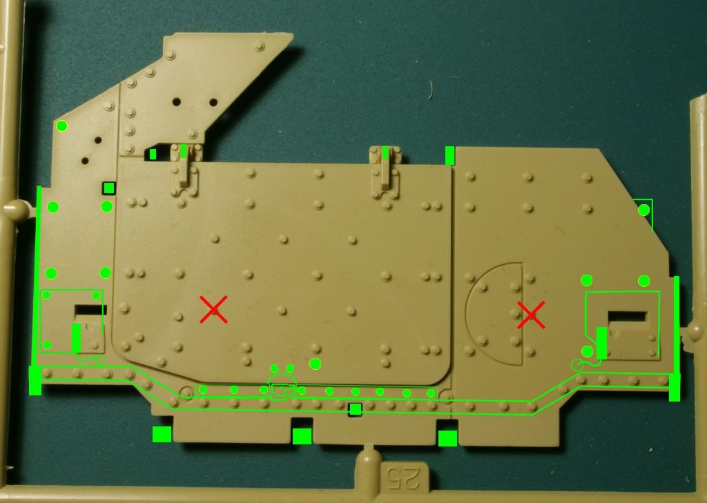
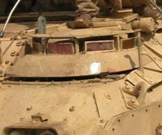
Front armor plate - part E25 - lacks a lot of details. But
there are also two extra bolt heads added by Tamiya, which should be removed
(see red crosses on the picture). A lot of bolt heads are missing from the kit
part - they are marked with green circles on the picture. One bolt is missing on
the right side of the picture, that is actually outside of kit part. This is
because Tamiya omitted the small triangular (with rounded corner) extension of
the armor plate, where this bolt is attached. I must admit that it is easy to
miss this detail as this area is hidden behind headlight unit or the side armor
plate on almost all photos. Two small lifting eyes are missing from engine
cover hinges. Another, even smaller lifting eye is located left of the left
hinge (as looking at the picture) in the gap between armor plates. One bigger
lifting eye should be above the upper right corner of engine cover. Base plates
for headlight assemblies should be bigger and there should be cables and metal
cable covers on them and close to these plates there should be holes in main
armor plate for electrical sockets and plugs. Under the engine cover there
should be two metal bars with big bolts on them and between them there should
be the engine cover lock (these bars and engine lock have been added to Tamiya
M2A2ODS kit as part F26). Other details missing are various hinges, hooks and
brackets associated with the swim barrier. There are holes for some of them in
the armor plate, but there is nothing in Tamiya kit to put in these holes. In
older M2A2 vehicles many (but not all) of these things are hidden under the swim
barrier (but not under part E12! - more info further in the article), so you may decide to ignore their absence.
But if you build ODS vehicle
you may need to add some of these parts, as they become visible once the barrier
is removed.
|
|
| Front armor
plate. Green color denotes details that have to be added, red crosses mark bolt heads that should be removed. Click on the picture to enlarge it. |
 |
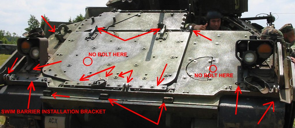 |
| M2A2ODS
vehicle with swim barrier removed. As this vehicle was originally regular
M2A2, all details shown are the same as they were in older vehicles before ODS changes.
Arrows point to details missing from Tamiya kit. Click on the picture to enlarge it. |
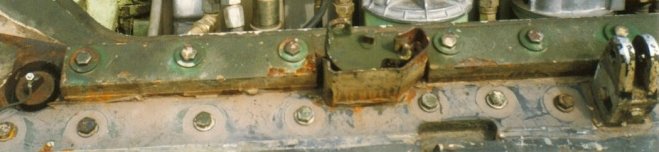
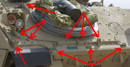
Another
M2A2ODS vehicle with swim barrier removed, but this time the long mounting
bracket was left. Swim barrier and its rubber cover were bolted directly
to this bracket. Arrows point to details missing from Tamiya kit. Also note empty places where Tamiya put bolt heads. Click on the picture to enlarge it. |
|
|
| Close up shot of engine cover lock. |
Above part E25 there is smaller part E32 attached. This is another armor plate and while this time no details are missing from the plate itself, there are two cutouts in it, which are empty in Tamiya kit. In reality there should be a small lifting eye in the upper hole and the larger "thing" (part of some hinge?) in the lower hole (see photos).
Largest part that is attached to the front armor plate in Tamiya kit is a rolled swim barrier (part E12). This part is too thin in the kit, is wrong shape and Tamiya want you to attach it in the wrong place! If you look at the front armor plate (part E25) you can see a long row of bolts at the bottom of it. It is straight around the middle of the part, but then bolts are a bit higher on both sides above mud flaps. Tamiya molded those bolts very accurately, but only for an ODS vehicle, that had the swim barrier removed! This is interesting as there where no ODS vehicles when those molds were designed... In pre-ODS vehicles there was a long bracket attached to these bolts (see one of the photos above) and the swim barrier was in turn bolted to this bracket - it is absent from the kit. So in fact swim barrier in the model should be attached over the molded-on line of bolts and should follow the shape of this line. But part E12 is straight and if you attach it according to instructions it will be a few millimeters below the line of bolts... It will be almost at the very edge of the armor plate, while in fact it is a few inches from the edge on the real vehicle - at least when it is tightly strapped. If it is loosely strapped (as is usually the case) it will drop lower on the armor plate, but it will still cover the line of bolts, or be immediately below it and will follow its shape. After attaching the kit part large gaps will appear under the part on both sides of it, above mud flaps - obviously they should not be there. I suggest replacing the front water barrier completely with some rolled metal foil. Of course tie downs and straps would have to be scratch built - they are molded on the kit part.
|
|
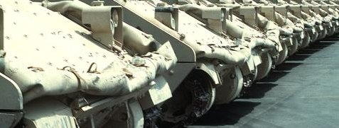
| Swim barriers on
front armor. Note how the shape depends on tightness of straps on various
vehicles. The barrier always follows the "wavy" shape of the line of bolts on front armor, as it is attached to these bolts. |
I strongly
suggest you get a Verlinden Publications Warmachines No.5 book, as there are
very good photos of front armor plates of M3A2 Bradley (they are the same as in
M2A2) on pages 27 and 28. Those pictures clearly show most things I mentioned
above.
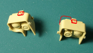
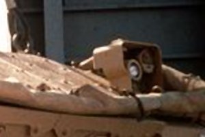
Main headlight units (parts E30, E33, E37 and E38) look good from the front side, although all cables are missing. Parts E37 and E38 have solid back plates, while in fact you can see through the headlight units in the real vehicle, particularly through the left one (see photos of front armor plate above). Things look much worse if you look at the headlight from above, as the brackets on top of each unit are reduced to almost nothing in Tamiya kit. But the biggest Tamiya error here is the back of the left headlight unit. Tamiya made it the same constant depth as the right unit, while in fact the left headlight cover extends further back on one side (see photos).
|
|
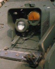 |
| Headlights from Tamiya kit. Red lines show missing details. | Note cables,
metal cable cover on a base plate and bracket on top of the headlight unit. |
 |
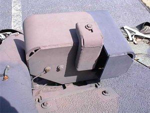 |
| Note the extended headlight shield. | Close up shot of
the back of left headlight unit. Photo RG |
Two large lifting eyes are attached to the front of Bradley (parts A36) - one on the front armor plate and the other on the first sloped side armor plate on the left side of the vehicle. Parts A36 lack prominent bolt details - You can make bolt heads from styrene sheet using hexagonal punch and die set or cut them from the hexagonal styrene rod (as I did).
Armor plates on side slopes of Bradley hull below driver's hatch are molded on the hull part C7. In reality these plates are thinner then the ones on the front slopes of the vehicle, but still those molded on the hull part look too thin. I suggest that you cut off all bolt detail, glue pieces of styrene sheet cut to shape (0.010" sheet should be enough to improve appearance of these plates) over molded on plates and then replace all bolt heads.
Driver's hatch is acceptable, although the hinge mechanism is a bit simplified and some parts of it are oversized because Tamiya made it working. One significant part missing from Tamiya kit is the curved hatch guide slab with holes in it. There is a latch in the hatch that interlocks with holes in the slab allowing for locking the hatch in three positions. This part can be added form styrene sheet. In front and to the left of driver's hatch there should be a metal part (a kind of hook) that is a support point for one of swim barrier tripods (see photo below) - again easy to add from styrene. Immediately behind the driver's hatch is the crew vent - it should be bolted to the hatch hinge, but in Tamiya kit it is separated from the hatch completely. I added styrene extension of the vent cover and a bolt to my kit. Air intake grille on the side of the vent cover is also missing from Tamiya kit - I used a piece of leftover PE grille from some old Eduard set to replicate it.
|
|
 |
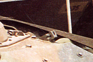
| Note the hatch
guide (green) missing from all Tamiya Bradley kits. On the bottom of this photo you can see the bolt on the triangular extension of the front armor plate, also missing from Tamiya kit. Metal pole on the right side of the picture is one of ODS modifications. |
Another picture of driver's hatch. Arrow on the bottom left shows the hook used to attach one of the swim barrier tripods (not present on newer ODS vehicle on previous photo). Also shown are two pipes welded to the armor, described later. Photo CP |
 |
 |
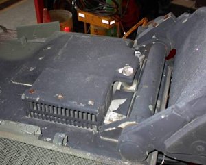
| Crew vent located
behind driver's hatch. It is a photo of M3 CFV, but it is exactly the same
as in M2A2 Bradley. Photo RG |
Close-up shot of
the hook used to attach one of swim barrier posts/tripods. Photo VP |
GO
TO PREVIOUS PAGE
GO TO NEXT PAGE
PART1 PART2
PART3 PART4
PART5 PART6
SUPPLEMENT
|
Most of the photos of real vehicles in this article came from various sources on the Internet. I have so many of them downloaded on my computer that I lost track of where each of them came from. If you recognized some of the pictures as yours and want me to credit you for them here, or you want me to remove them, let me know - I'll sure do it. |
![]()
![]()
![]()
Copyright © 2004 VODNIK, mailto:pawel@vodnik.net